|
So far, we have calibrated our feed and flow rates to get good extrusion, but some of the fine details in certain prints can be difficult to get good fill on. Well, here is where we fix that. In Slic3r configuration, in the Print Settings tab, there is a choice called Advanced. This is where we make magic happen Load up a model that has fine surface details - like lettering. Lettering is notoriously difficult to make look good with the various shapes of each letter. I will be using a small tag I created to print color samples in. This tag is 40mm wide x 38mm tall and the base is only 2mm thick with the letters being another 2mm - not very big. 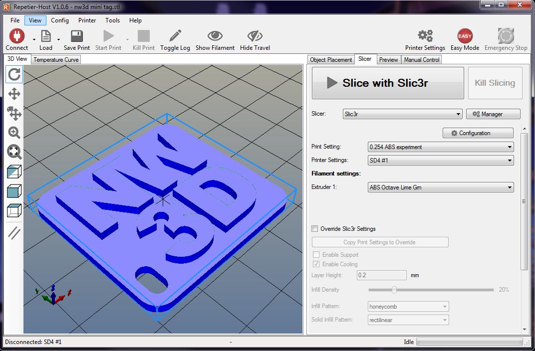 model loaded and ready for slicing After loading our model, we go to the slicing tab in Repetier Host (RH) and click on the Configuration button and open Slic3r's configuration window and click on Advanced in the left menu. You should see something like this: 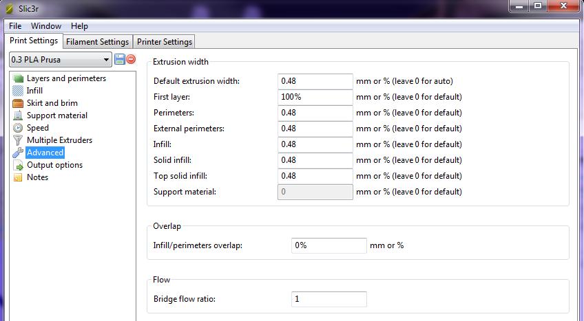 If this is the first time you have ever used this tab, your numbers may be different than what is shown here, more likely to be almost all zeros with the exception of the First Layer setting which probably says 200%. The first thing you want to do is specify the Default extrusion width (top box), if you haven't already. That number, once set, should remain the same until you physically change nozzle size, and should be 120% of your nozzle diameter. I use primarily 0.4 nozzle size, so my default is 0.48 (0.4 x 120%). The other numbers shown above are all equal to the default extrusion width, which means everything will be at 100%. now lets slice our model with those settings and take a look at it. 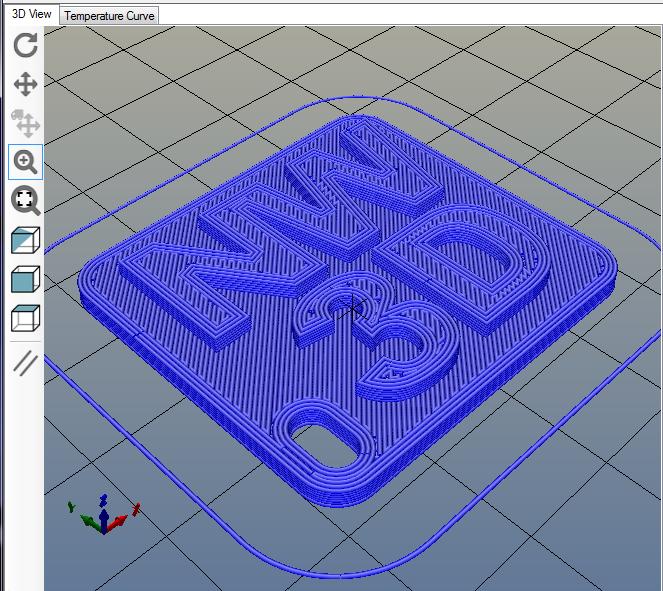 At first glance, it doesn't look too bad...but lets look closer. 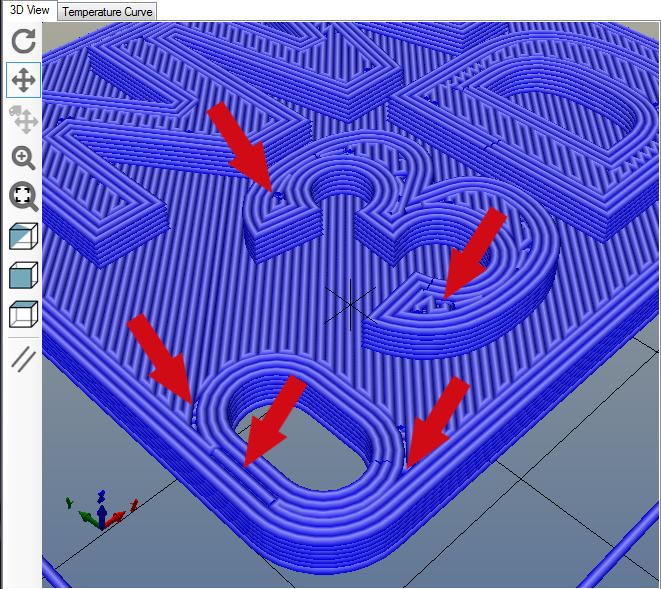 Notice the gaps in the areas the arrows are point to? These areas, when actually printed won't look very nice. So how do we fix it? Simple, we tweak extrusion width settings. Lets go back to Slic3r's Advanced settings and make some changes... 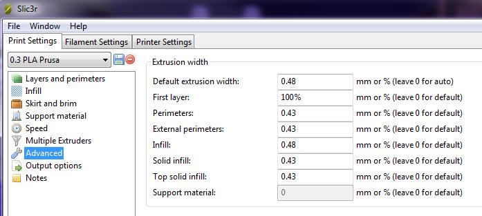 First thing to notice is that we left the default setting alone. That one should not change unless you are changing nozzle sizes. Just about everything below that, however, has been tweaked. Whenever you make a change in the settings, be sure to click the save button, then re-slice your model with the new settings and see how they have affected the model. 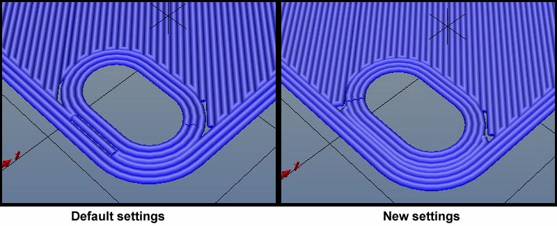 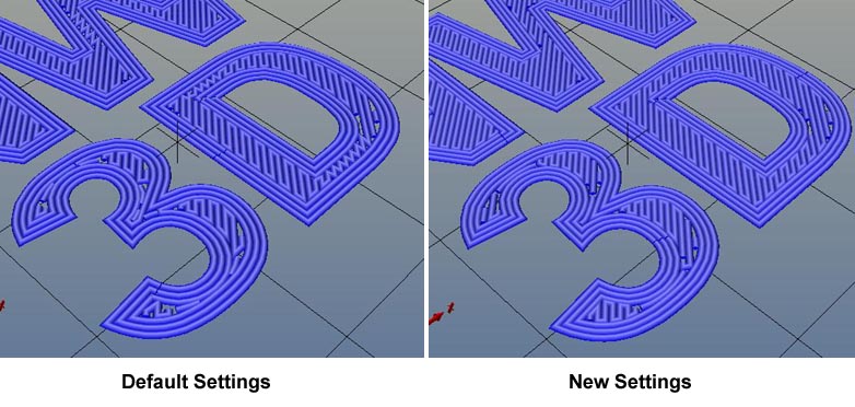 As you can see, there are differences between the original default settings and the new settings, but we still have a few gaps that need fixing, so back to the advanced settings we go and tweak a little more... 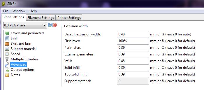 Again, make sure you save the new settings, and re-slice your model. Lets take a look at what that did. 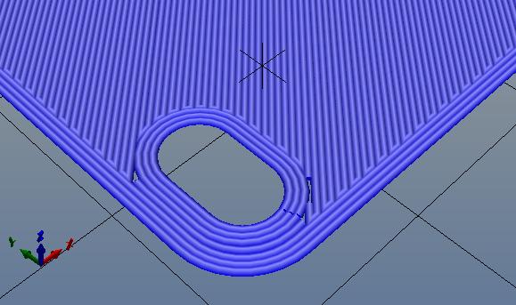 The top layer of the base looks pretty good.... 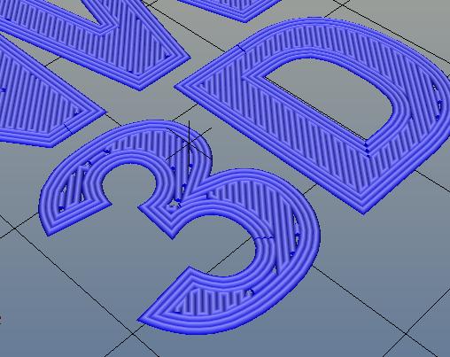 ....but the lettering still has some ugly gaps. To fix those, we continue tweaking the settings until we are satisfied with the overall look of the fill, keeping in mind that curved areas will never be 100% perfect. Just for fun, I went a little crazy with tweaking the extrusion widths and ended up with these settings... 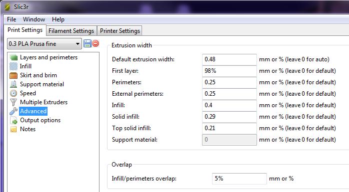 Resulting in this for a sliced top layer in the model... 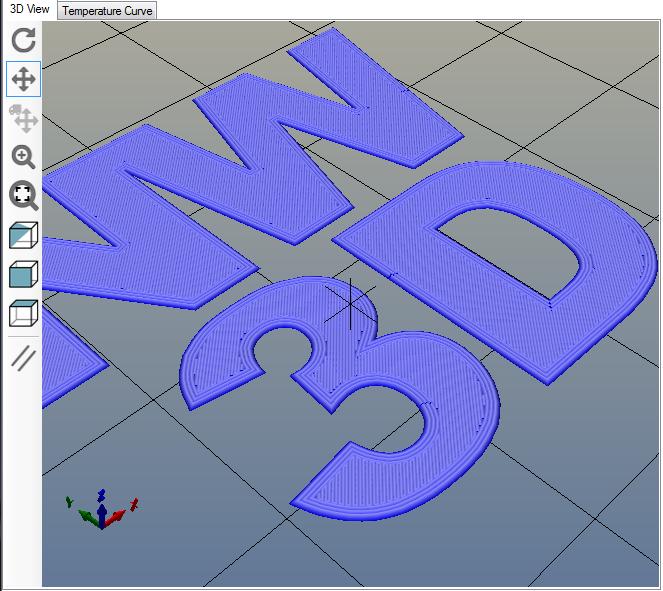 Please note that the Default extrusion width never changed throughout this process. For the record, yes, I have printed using similar settings as the last settings screen shot. It does work.
Slic3r does have more advanced settings in the stand alone version where you can set things like different layer heights for a single model, and use modifiers to set different infill rates for certain areas of a single model, but those are for another day. ~~~~ Time to go melt some plastic! Now that we have the filament diameter and feed rates calibrated, we need to calibrate for flow. Again, too much or too little will affect print quality and accuracy. Flow rate (how much plastic is coming out?) We will be printing a single wall test cube, but only about 8-10mm high. We don’t need to do the whole cube. There are a multitude of test cubes on thingiverse, and other sites, the size doesn’t really matter much - a basic 20mm x 20mm cube will work fine, it is the settings that matter here. In Slic3r, under the Filament Settings tab, set the extrusion multiplier to 1 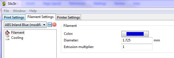 In the Print Settings tab of Slic3r, in the Layers and perimeters section, we want to set layer height to 0.3, we want a single perimeter, 0 top layers, and 2 bottom layers 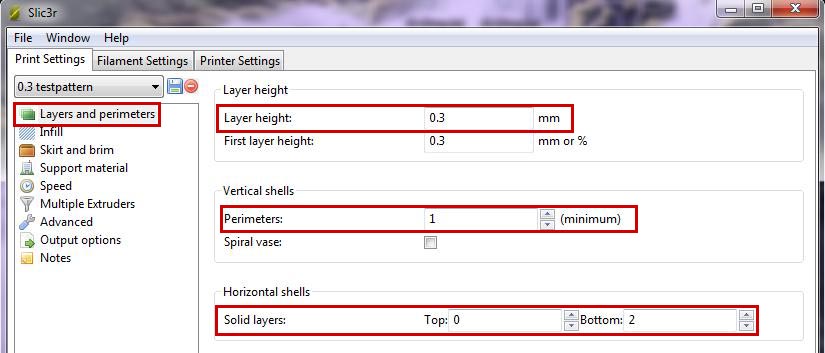 For Infill, we need to set it to zero 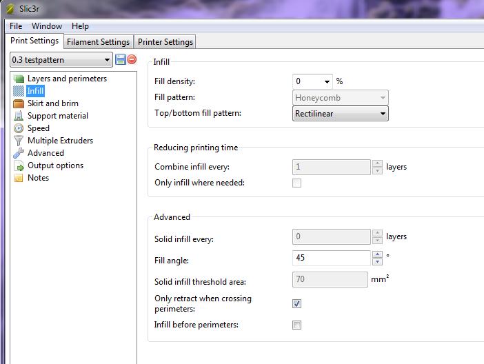 And lastly, in the Advanced section, we need to set the default extrusion width. This typically should be 120% of the actual nozzle diameter. For a 0.4 nozzle it will be 0.48; for a 0.35 nozzle, it would be 0.42, and so on. My printers all currently run 0.4 nozzles. 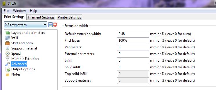 I like to set the first layer to 100%, but you can set it to more for better adhesion if you like. Make sure you save your settings! Print one copy of your test cube, approx 8-10mm tall (roughly 25 layers) - it should look something like this when done. 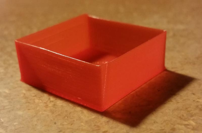 Get out your calipers and measure each wall of the cube after it has completely cooled (if it is still warm you could deform the plastic when measuring and not get accurate readings), near the center of the wall. Try to grab only the top 1 or 2 layers of each side as shown below. 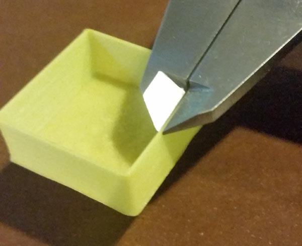 Make a note of each measurement and take an average of the wall thickness. The number we are looking for here is the same number as our default extrusion width - in this case 0.48. More than likely, your first run will be larger than this, so we will need to make an adjustment to the extrusion multiplier to correct it. The math is simple: desired measurement / actual measurement = extrusion multiplier Say our wall thickness averaged out to 0.5075, our math would be 0.48 / 0.5075 = 0.9458... So we want to enter 0.94 in our extrusion multiplier box (i have found that rounding down usually works better than rounding up and 2 decimal places is usually sufficient, 3 if you are having difficulty getting it to come out right). 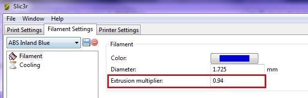 Don’t forget to save your changes! Re-slice your test cube with the new settings and print another test box and measure the walls again. You should be pretty close to the desired 0.48 wall thickness. If not, you can tweak the extrusion multiplier by hundredths up (if too small) or down (if too big) until you get the desired wall thickness 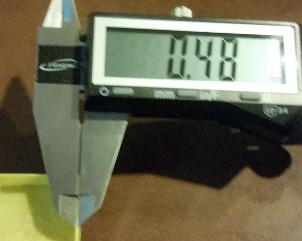 Now you are ready to print amazing projects! Keep in mind, this will need to be done for every roll of filament you use - every roll will be slightly different - even 2 rolls of the same color, from the same vendor, will be different. Slic3r is great because you can save the filament profile for each roll/color you have. It makes switching materials as easy as selecting the correct profile before slicing your model. 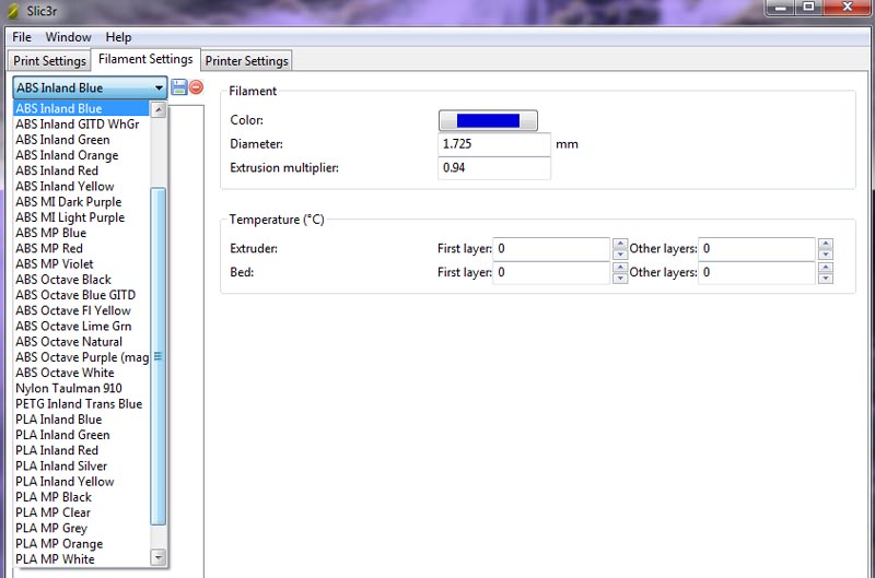 Yes, I really have that many profiles saved, LOL.
Once you get the hang of doing these calibrations, you can accomplish them in about 15 minutes, and it really does make a difference in how your prints will turn out. Next time we will explore making changes to our slicing profiles to get good infill in small areas. ~~~~~ Time to go melt some plastic! Disclaimer: I run a highly modified Solidoodle 4 running on Marlin firmware and I use Repetier Host and Slic3r for my printing software. All of the following calibrations have been done using the above equipment and software. Other software and equipment may differ somewhat in values and how things are entered/changed, but the calibration math should remain a constant. Every new roll of filament is going to be slightly different from last one used. Each roll should be calibrated to its specific characteristics. The following calibrations should be done for each new roll of filament you run to ensure consistent, accurate prints. Filament Diameter While the filament we buy is supposed to be of a certain size - either 1.75mm or 3mm - manufacturing does cause some inconsistencies in these diameters. So the first step in calibrating a new roll of filament is checking diameters. Tools needed
1. Load the spool up in your spool holder and pull a couple meters/yards off the spool. 2. Grab your digital calipers and take measurements along the length that you have pulled off the spool at random distances, making note of the measurements on the paper. 3. After taking a bunch of measurements (do at least 7, more is better), add them all up, then divide by the number of measurements you took to get an average diameter. 4. The average diameter is the number you want to enter into your slicing software for filament diameter. 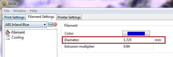 (All screen shots in this article are of Slic3r v1.2.9) Make sure you save your settings! Tip: If you like to change colors often, save a new profile for each color with that color’s specific settings. It is then just as easy as selecting the correct color profile for a filament when swapping colors. Feed Rate (how much plastic is going in?) After finding your filament average diameter, it is a good idea to check the feed rate to make sure it is feeding the expected amount of filament into and through the extruder. Too much, or too little, will affect your prints. Tools needed
Load the filament into the extruder, and heat it up. Drop the bed around 30-50mms so you have some space to free extrude. Once the extruder is up to temperature, feed a little filament through manually so that you know the hotend is fully loaded as it would be during printing. Make a mark at 100mm on the filament from the top of the extruder housing. If this is your first time doing this, I would also make a mark at 150mms (in case it feeds more than 100mms) 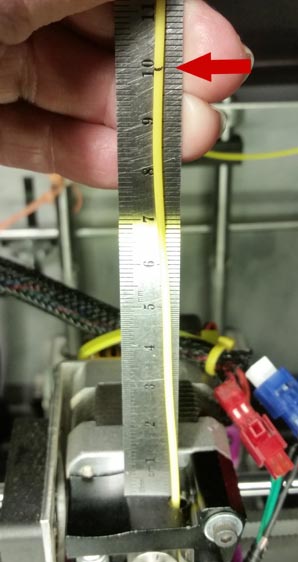 After making your marks, manually extrude 100mms of filament. If your 100mm mark is now at the top of the extruder housing, you are done. The feed rate is fine. 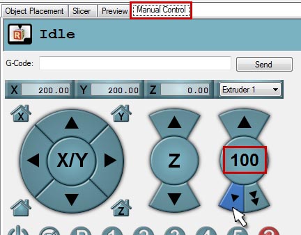 If your 100mm mark is not at the top of the extruder housing, you need to calculate the difference between the requested feed, and how much it actually fed through. If steps/mm are too low, your 100mm mark will be above the extruder housing - if steps/mm are too high, your 100mm mark will be below the top of the extruder housing (possibly even so far below that backing up the filament will not show it to you - did you make the mark at 150mms?) Measure the distance between the measured mark(s) and the top of the extruder housing to determine the difference of actual feed to requested feed. If your 100mm mark is above the extruder housing, measure the distance between the two and subtract that measurement from 100. This will give you the actual filament fed through the extruder. If your 100mm mark is below the top of the extruder housing, measure the distance to the 150mm mark, and subtract that from 150 to obtain the actual feed amount. Now for a little calculation... to determine the correct steps per mm for the extruder, the formula is: (expected length* x current steps per mm) / actual length = new steps per mm. *expected length is the 100mm you asked for Examples: Feeding more than 100mm: (100 x 138) / 143 = 96.50 Feeding less than 100mm: (100 x 138) / 96 = 143.75 There are several ways of entering the new steps per mm value into your printer’s firmware settings; it all depends on what printer you use, the firmware it is running on & the printing host used. The fastest and easiest method (for sprinter/marlin firmware) is to manually enter the value in the g-code command box in your host program. Enter the following commands:
Feed a few mms of filament through after saving to be sure the new settings have taken effect and then re-mark and feed another 100mm to verify the settings are correct. You may find you need to tweak the new e-steps just a little to get it exactly where you want it to be. If your firmware has EEPROM enabled, you can make the changes in that quite easily. To check if EEPROM is enabled, go to the top menu of RH and click on "Config" - if "Firmware EEPROM Configuration" is black, it is enabled and you can click on it to open. If it is greyed out, it is not enabled and you would have to enable it in the firmware and re-flash the firmware to your printer's controller board. Open EEPROM (if it is enabled) and type in the new steps/mm in the appropriate box - the one marked “E” 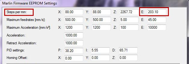 Then click on the save to EEPROM box at the bottom of the screen 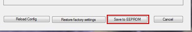 A new window will pop up asking if you are sure you want to save to the running configuration - click yes.
And your new settings are in place. To verify the new settings are correct, feed about 10mms of filament so the system will compensate for the new settings, and then repeat the above steps to make sure you are getting 100mm when you ask for 100mm. In Part 2 we will cover how to calibrate the Flow Rate (how much filament is coming out). Stay Tuned! ~~~~ Time to go melt some plastic!  Note: For the purposes of these discussions, I will be using either my favorite Solidoodle 4 or my FolgerTech 2020 Prusa i3 printers. Both are Cartesian style printers, but different in how each axis moves. I also use free software - Repetier Host to communicate & control the printer, and Slic3r as my go-to slicing software. Both of these programs are completely free to download and use. So, you have your 3D printer and you are all excited to print some of the amazing stuff you found on Thingiverse, or other stl sharing website… but hold up, partner! You need to do a little work first if you want truly nice prints. To start with, read the manual! Yeah, yeah, I know what you are thinking - “I don’t need no stinking manual!”, but you would be doing yourself a favor if you do read it. Some printers come with a printed manual, others you need to go online and download it - either way - read the darn thing! Learn how YOUR printer works, how to turn it on/off, how to load the filament, how to level the bed, etc. With the multitude of printer designs out there, they are all slightly different. Next, you should make sure everything is nice and snug - no sloppiness anywhere. Belts (if yours has them) are tensioned properly, all screws are tight, and so on. Loose fasteners will cause you no end of headaches. Belt tension… Sloppy belts will cause axis shift problems. Belts should be tensioned enough that they do not vibrate doing movements. On my printers I will set the carriages all the way to one end of travel and then pinch the belt about halfway between - on a Cartesian type printer they should be tight enough to just barely meet when pinched with a bit of resistance. On a Delta/Kossel, the longer run won’t give as much resistance when pinched, but they should still not vibrate while the printer is running 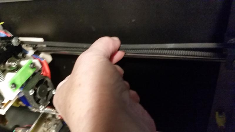 If your printer does not have an easy way of tensioning the belts, you will probably want to look for possible upgrades that will make it easier to do so. Belts do stretch over time and will need to be adjusted occasionally. Many of the Prusa type printers tend to use springs to increase belt tension. This, in my humble opinion, is not the best way of handling the situation. A fully adjustable option is far more useful and easier. OK, we have belts tensioned properly - can we print yet? Nope, not just yet. Now we need to level the bed so we get a good 1st layer down. Just like with a building we need a good foundation for our prints. If the first layer is not put down well enough, we will have all sorts of issues with the remainder of the print. Bed Leveling…. Most Cartesian style printers have either 3 or 4 bed leveling screws. These screws help us fine tune the bed to nozzle level, or gap. Bed “leveling” can be a bit of a misnomer - we are not leveling with a bubble level to make sure it is perfectly flat and level to the ground - we are adjusting the gap between the nozzle and the bed so that it is the same across the entire build plate. There IS a difference. To start with, we need to adjust the Z axis endstop to get the nozzle close to the bed. Tighten the leveling screws to about ½ of their travel. This will vary depending on the length of the springs used. You want a fair amount of tension on those springs before you even start making adjustments. Home the printer using your host program. Then move the printhead using the manual controls so it is over the middle of the bed (make sure there is no filament sticking out of the nozzle from ooze - if there is, use a razor or exacto blade to trim it off - you want bare nozzle for this). Adjust the Z endstop so the nozzle is about 0.5mm off the bed with the printhead in this position (a piece of cardboard from a cereal box or soda carton would be very close). The exact procedure will vary depending on the printer, some have an adjustment screw, others you may need to move the endstop mount itself. If you have read your manual you will know what you need to do. You will want to preheat the bed to the desired operating temperature. We will be “leveling” with the bed warm - not cold - as the temperature will affect the gap between bed and nozzle. Typical temperatures are For PLA: 50 to 60C For ABS: about 100C You will want to repeat the process when switching between bed temps - it DOES matter! Once you have the Z endstop adjusted, move the printhead using the manual controls so it is nearly over one of the leveling screws. You don’t have to be directly over it, but close 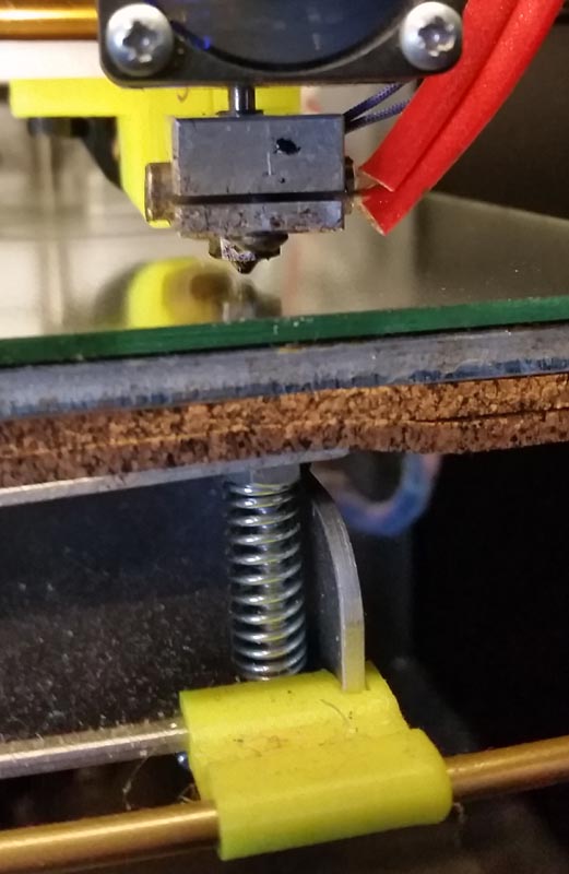 Using a piece of standard copy paper (0.1mm thick), slip it between the bed and nozzle, then adjust the screw until you can just feel a little bit of drag on the paper when you move it. There should be just a very slight resistance when moving the paper under the nozzle. You don’t want it to be digging into the paper, or tearing it. 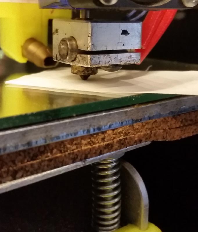 Repeat the process for each leveling screw your machine has. Be sure to check each location again after the main adjustment is completed to make sure everything is where you need it to be. Often, adjusting one location may change another slightly.
Once you have things where you think they need to be, verify in several places across the build plate to make sure the gap is consistent. If you find it is not - either too low or too high in some places, then you may have a warped bed and will need to modify to get a perfectly flat surface. Glass is a very good choice for this. Either plain window glass, or a piece of mirror, cut to the same size as your bed works beautifully. You will want something that is about 3mm thick (1/8th inch) - any less and you run the risk of it cracking in the heat/cool cycles. To hold the glass in place, go to your local drug store and pick up a can of Aqua Net Super Extra Hold hairspray (unscented - in a purple can). Spray one side of the glass - get it damp, but not runny. Set the glass on the bed and heat to 60C, turn off the heat and let it cool completely. Repeat 2 or 3 more times and the glass should be firmly fixed to the bed. Then go through the leveling process again, beginning with adjusting the Z endstop. So we now have a nice, level bed - ready to print, right? Not quite yet… Stay tuned for the next posting where we go over calibrating our feed and flow rates. Time to go melt some plastic! As a member of 3d printing forums and Facebook groups I see a lot of new folks asking the same old questions - What is wrong with my prints? The plastic isn't meeting at the edges/looks blobby and uneven - How do I fix it?
It seems that lately the most common answer given is "buy Simplify3D" - a $150 program that has no free trial. True, they do offer a 2 week "money back guarantee", but that is not the same thing as a free trial. And, in all honesty, it is not the be all, "end all of your 3d printing problems" program that some try to make it out to be. You still need to learn how to use it correctly if you do cave in and buy it. Otherwise you have just wasted your hard earned dollars. My theory is this - if you take the time to properly set up and calibrate your printer and your slicing software you can save that $150 and put it towards something else - more filament, start saving for another printer, spare parts or upgrades, etc. I use programs that are free and open source and my prints look just as good, if not better, than those printed using expensive software. Why? Because I have taken the time to learn how to properly calibrate my printer and set up those free programs. It isn't hard to do, but it does require that you make the effort. Over the next few posts I will go over the basics of good calibration techniques on "open source" printers and using completely free software - including:
Time to go melt some plastic! |
